I've only changed 2 belts on a John Deere 2653 before but that was enough for me to realize I didn't want to do any more of them. Anyone that has changed one before knows how big of a mess and time consuming it is. I've done the trick of putting on two belts and zip tie one to the fan shroud so when one breaks the second is there and ready to go. My complaint is any repair in the category of "Maintenance on a wearable item" should be as simple and quick as possible. However this one isn't.
With my woodworking hobby I have come across several link belts and always wondered if it would work in this situation. I put one on a 2653 in summer of 2012 and it is still going strong. The belt cost is 33.99 and goes on in 20 minutes instead of 4 hours. The nature of link belts are they run quieter and cooler so there is less stretching. If you have a belt that is troublesome to get to, try this belt. It may be the missing link to an easy repair.
I updated this post and included a pic of the link belt part number and some description. The OEM belt has an effective length of 34 inches and 1/2 wide. You'll need the 1/2" wide link belt in the 4' section. Pay attention to the arrows printed on the link belt. It will tell you the direction the belt needs to travel for proper operation. When you're done with the install you'll just have a short section of belt left over.
Wednesday, November 12, 2014
Monday, August 18, 2014
Granite Surface Plate and Stand
I've wanted a good surface plate for quite some time but was making a metal parallel plate work as long as I could. I finally found a plate and stand combo priced really well. I got it from MSC Direct as a combo set for 360. The surface plate is "Grade B" or tool room which is more than accurate enough to do what I'm doing with it. As you can see I made some modifications on the stand. I wanted it to be level with my lift gate on the back of the grinder. I will add a plywood bottom for storage and to prevent the top of the surface plate from being a place to lay tools.
When I get a reel ground, I can roll it off the lift gate right onto the surface plate and perform the checks. I also added some arms to each side. One set allows the reel to roll over the drop lip of the lift gate onto the surface plate. The other allows me to roll the reel off the surface plate and check/set the reel without flipping it upside down.
I finally added the bottom. I used a router and mounted a square piece of steel into the plywood so my magnetic indicator would have a place to stick.
I put 1000 lb swivel casters on it for easy moving. The caster plates were so big I had to weld a brace in to accommodate the bolt holes. Two of the casters are lockable.
When I get a reel ground, I can roll it off the lift gate right onto the surface plate and perform the checks. I also added some arms to each side. One set allows the reel to roll over the drop lip of the lift gate onto the surface plate. The other allows me to roll the reel off the surface plate and check/set the reel without flipping it upside down.
I finally added the bottom. I used a router and mounted a square piece of steel into the plywood so my magnetic indicator would have a place to stick.
Thursday, May 1, 2014
Toro 7 Gang Hydraulic Valve Upgrade
The course purchased this Toro Gang mower new in 1988. Originally it was used for fairway during grow in. For the last 20 years it has been our primary rough mower. We mow rough at least two times a week from April through September. It is responsible for cutting a lot of turf.
In the spring of 2013 our director of agronomy asked me if I could install an electric over hydraulic valve for raising and lowering the cutting units. Raising and lowering the cutting units has always been a cumbersome task. One has to actuate the valve on the tractor with one hand and reach behind the tractor with the other hand to actuate the valve for the cutting unit. Below is some pictures of the original valve. There are 5 spools in this valve. The center one operates number 1,2 and 3 cutting units. The one left of center operates number 5 cutting unit. Left of that is number 7. Right of center is number 4, then number 6.
I started the search for the valve on the internet. I found the Cross Company out of Greensboro, NC. They are a distributor for Walvoil valves. After talking to Walvoil we decide the valve we needed was model 18ES3(X5)/RC-SAE-12vdc. The valve came complete with solenoids. There is a solenoid on each side of the spool to make it bidirectional. I also ordered the Canfield connectors part # 5F6C4-000-HUOA from Cross Company. They are 12 feet long and connect to the solenoids.
Next I needed to make a control box. I turned to Mouser Electronics out of Mansfield, TX. They have everything electronic. With my Toro back ground I wanted to use Carling Switches. The switch I needed was a double pole double throw switch. It is momentary on, off, momentary on. I purchased all the electrical components from Mouser. If you would like a parts list please email me.
Here's the wires connected to the lower solenoids.
Now it was time to install the valve. I mounted the valve in it's originally location. I had to fabricate a plate for the valve to rest on. It is slightly larger than the original plate. The original valve had -8 SAE ports. The new valve has -6 SAE ports. I ordered the adapters from Grainger.
If you have any questions please email me. Trent Manning
In the spring of 2013 our director of agronomy asked me if I could install an electric over hydraulic valve for raising and lowering the cutting units. Raising and lowering the cutting units has always been a cumbersome task. One has to actuate the valve on the tractor with one hand and reach behind the tractor with the other hand to actuate the valve for the cutting unit. Below is some pictures of the original valve. There are 5 spools in this valve. The center one operates number 1,2 and 3 cutting units. The one left of center operates number 5 cutting unit. Left of that is number 7. Right of center is number 4, then number 6.
Then I started the wiring process. The 2 white wires on the right side of the box are the main power. These wires went to the center tabs of the first switch. I used a short jumper to power the other switches. For all the wires coming in the box I used Heyco liquid tight cordgrips. Each spool on the valve has 2 solenoids, one for raising and one for lowering. The wires that come into the box in the bottom cordgrips are for the lower solenoids. The wires in the upper cordgrips go to the raise solenoids.
Here's control box after it was finished
Here's the valve installed!!!
Thursday, March 6, 2014
Blower rack on JD 2500
This started out as an idea to prevent a separate guy from having to drive around in front and behind each triplex mower blowing debris and clippings. We need a blower rack on the triplex but where? There isn't a good place with access to the frame on the JD 2500. It needed to accommodate a stihl or redmax blower, not impede operator view and not have to be removed to service anything. Between the ROPS was the only real option for location. So, I drew it up on paper and it actually turned out like it was supposed to. Go figure...
All total I spent around 3 days building this rack. It could be done in 4 hrs now that I have the layout. I added the 3/4 square tube to this rack because I didn't have enough angle. This steel was ordered for racks on trailers but turned into a rack for triplex. The bushing is a club car front leaf spring spacer that I cut a 1/4" length off for each side. I put a bungee on it and bent the hooks closed so it can't be removed. The operator simply lifts the bungee up and and over the blower backrest to remove blower. The only thing I'm going to change on this one and the second one is to make the lower bolt (the one the rack rests on) a 4.5" long carriage bolt and put a spacer on it for the rack to rest on. If you have any questions about this just ask. cphillipsgolf@gmail.com or on twitter @CAPgolf
Getting the geometry worked out for the bolt holes was quite fun. Haven't used that Math in a while, good to know I still can though. |
Wednesday, March 5, 2014
Cocoa Mat Repair
This one involves our Cocoa drag mat. I have seen several of these at various golf courses and nearly all of them had a rip or small tear on them. This mat is heavy and most operators have to pick it up after each green. So, by the time they reach the 4th green they tend to drag it out of the cart bed. This is usually where the tear starts. I've been told once a tear starts you try and minimize it until the mat isn't usable anymore. I started looking into rubber bonding compounds. I found this Devcon Flexane 80 Urethane from Grainger and started doing my research into it. It is offered in a putty form and a liquid form. After reading up on both I chose the liquid form because it has a higher tensile strength at 2100 psi and I thought it would flow into the tear and fill the cracks better. Hindsight being 20/20 I should have went with the putty. It has a tensile strength of 1700 psi and it would have been easier to apply and work with after applied. However, back to the mat. I took my grinder with a sanding pad and buffed the areas around the tear until it was smooth. This process also heats up the rubber on the cocoa mat. I then drilled two holes across from each other on the outer edge of the tear. I used a med sized zip tie through these holes to help pull the tear together and hold it while the rubber compound set. I mixed the rubber compound and poured it on the tear. I poured fairly slow to allow the compound to flow into the cracks. Here is where I wish I would have chosen the putty form. I didn't have the tear pulled tight enough together and the rubber flowed through the tear and down onto the floor. By the time I got there the next morning, the cocoa mat was stuck to the floor. I was able to get it free with little effort but I had to cut a couple nickle size chunks of rubber out of the cocoa fibers on the bottom of mat. I completed this repair for 75.00 and a new drag mat would be a LOT more than that.
Here are some before and after pics of the repair
Saturday, February 15, 2014
Bunker Tiller
We purchased a Honda FG110 to soften the bottom of the bunkers when they become too firm. Here was the problem, how do we keep the tiller from going too deep and tearing the bunker liner. I looked around the shop and found some 1" square tubing, 3/4" square tubing, 1/2" round bar, u-bolts and some gage wheels for a JD 757 (JD part# TCU18744). It's amazing what you can find around the shop. I attached the 1" tubing to the handle bar with the u-bolts. I drilled 3 sets of holes in the 3/4" tubing to make it adjustable. The gage wheels fit perfectly on the 1/2" round bar. The end of the 1/2" bar has holes with cotter keys installed to hold it all together. I used spacers and washers to get the 3/4" tubing space correctly. With the gage wheels set to the deepest setting the tiller goes about 3" deep.
Stimpmeter Holder
Here's a Stimpmeter holder that I installed on a E-Z-Go for our director of agronomy. The holder is made from two, 2" cushion clamps that were purchased from Grainger (Part # 2UTG2). I installed them with self drilling screws. This is a very cheap and easy install. It also allows enough room to carry a putter. We have been using these for 20 years and the director would be lost without it.
Friday, February 7, 2014
Brake Spring Addition
I'll start this out
by saying that all my fixes, fabrications, and improvements are brought on by
a problem of some sort. This one is no different. The Machine is John Deere 220
E-Cut. The problem is with the park brake cable. It rusts and with it's location is prone to being hit with another mower if you use the 22B WBGM double greens mower trailer.
(This photo shows how it is originally. As you can see I added the rubber nipple on the end of the cable to help with moisture. I use a water resistant spray grease with a straw on end of spray tip. Stick the straw inside the cable housing and fill it up. Put the rubber nipple on and no more rusting cable problems.)
The double trailer for our greens mowers aligns the front reel pivot on one greens mower with the park brake cable of the other when they are loaded on this trailer. (No, They aren't loaded on a trailer in this photo but it shows how they align to cause damage to the brake cable.)
After one good whack on the park brake cable the housing bends or breaks and the cable will bind when its engaged. Since the park switch is under the handlebar assembly the controller will think the brake is disengaged when the handle is released. So, the operator engages the mower with the park brake band still tight because of the sticking cable and I get heat, slow traction speed, poor cut quality due to clip rate being off.
(As you can see by this photo, the cable actually broke at the adjustment nut.)
My solution to this problem is a simple spring I purchased through Grainger (part number 1NBX5 pack of 3 that are 12" long for 10.00) cut and installed on the park brake cable end just like the traction cable has. I cutting them into 2.125 inch lengths. The spring is strong so it will release the park brake band even though the cable may be bound up pretty bad.
I'm still not happy with the location of this cable but this is a simple band-aid until I find time to come up with a better solution or a better way of teaching operators not to hit them.
Thursday, January 30, 2014
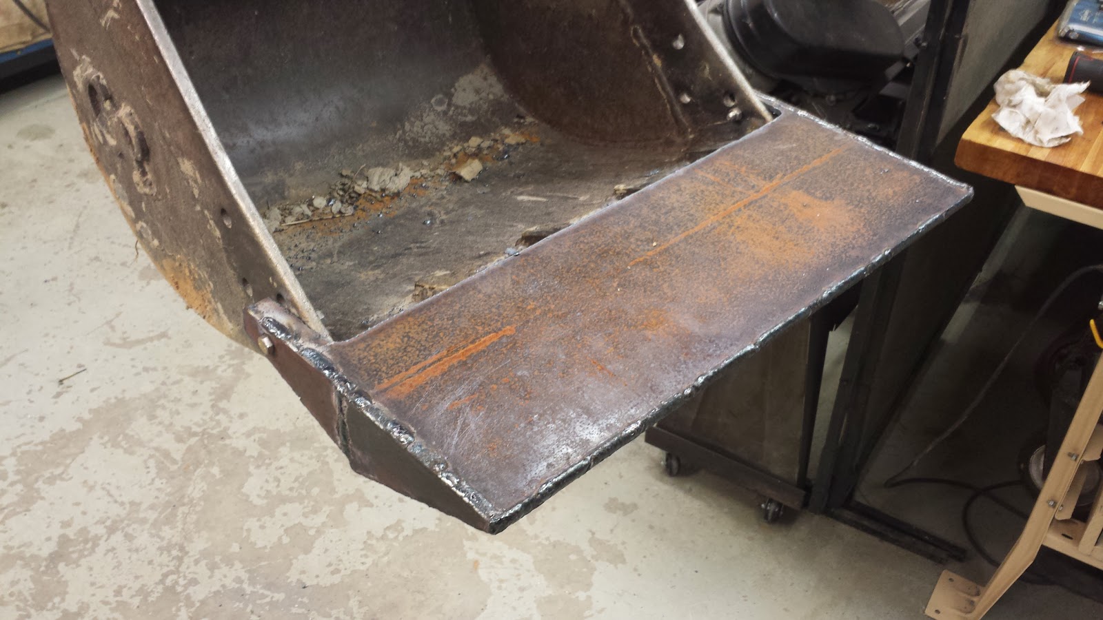
Smooth bucket attachment
We had a need for a smooth bucket for our Takeuchi TB135 mini excavator. A smooth buck cost around $1100. I built this attachment for $80. I purchased a piece of 1/4" plate from my local steel supplier. The plate measured 12 inches by 72 inches. First, I cut two pieces with a torch, for the top and bottom of the bucket. I tack welded the two pieces together. Then, I cut four more pieces to close in the sides. I welded all of the pieces together with the arc welder. After everything was welded, I drilled a 3/8" hole through the plate and the bucket. When drilling holes in metal I always start with a small bit and work up to the final size. In this case I started with a 1/8" bit. I usually step up in 16th inch increments. This helps reduce the wear on the drill bits. Another mistake I see is using a cordless drill at full speed while drilling through metal. This will also shorten the life of your drill bits. Think about it like this, drill presses turn at a low RPM for a reason. I drilled holes on both sides of the bucket and attached the plate with grade 8, 3/8" bolts for easy installation and removal. The project can easily be completed in a day, it took me around four hours.
Here's the finished product |
Side view |
Top view |
Bottom view |
Subscribe to:
Posts (Atom)